Stresses Beneath Pads Under Eccentric Loads, Shears and Moments Spreadsheet
15 July 2019Stresses Beneath Pads Under Eccentric Loads, Shears and Moments Spreadsheet
EccPad is an Excel spreadsheet for the calculation of pressure induced beneath rectangular pads subjected to eccentric loads, shears & moments. The pressure distribution can be linear no-tension, linear tension allowed or uniform no-tension.
Using its analysis, pads can be sized to limit the induced vertical pressures and to have adequate safety factors against overturning in two orthogonal directions.
EccPad helps reduce design time by avoiding cumbersome hand calculations. In a design process, pad data can be saved and retrieved for repeated optimisation.
Features
- The pressure distribution beneath the pad can be Linear-Tension-permitted or Linear-No-tension or Uniform-No-Tension. A pull down menu allows a selection from these three analysis options.
- Analysis can be in any consistent units of force and length e.g. kN m, lb ft, etc.
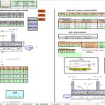
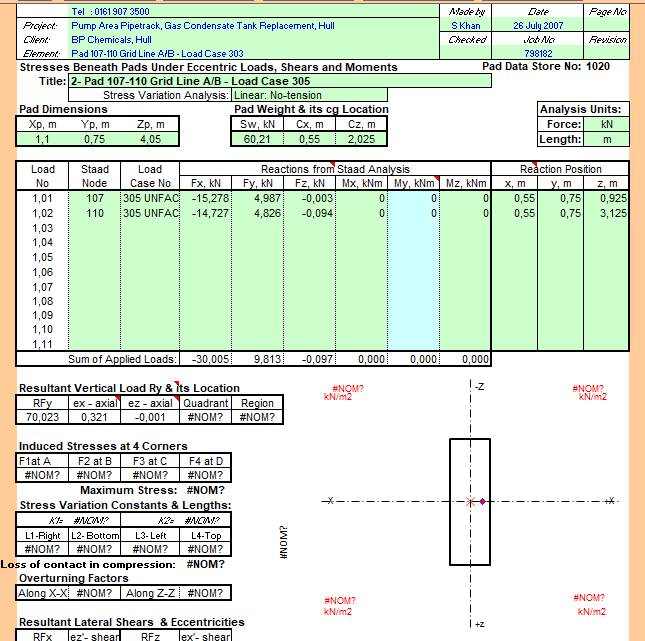
- A diagram displays pressure distribution at corners and along edges of the pad on the screen display. This allows comprehension of the induced pressure distribution at a glance when meeting design and commercial requirements.
- The diagram also displays positions of both the axial and the shear resultants.
- Overturning factors in the x-x and the z-z direction are calculated and shown in the screen display and output. This allows a check of pad stability at a glance.
- Percent loss of soffit area in compression is calculated and displayed when the analysis is non-tension. This helps sizing of pads and improve their stability.
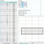
- Reactions from Staad Pro or similar programs can be copied to the clipboard and pasted into EccPad. This reduces input errors and expedites the design process. No sign adjustments are required when the input is from Staad Pro.
- Induced pressures are calculated at all four corners of the pad and noted in the screen display.
- The distribution of mass in the rectangular pad can be non-uniform. To this end, self weight of the pad and its centroid is input as data.
- In addition to the self weight, eleven other loads can be applied in each EccPad analysis.
- Each applied load can have 8 components i.e. Fy, Fy, Fz, Mx, My, Mz as magnitudes and x, y, z as their position from top lower left corner of the pad.
- The induced pressures are calculated at soffit level of the pad. As applied loads act on top of the pad, the additional moments equal to horizontal loads multiplied by the pad depth are taken into account in the analysis.
- When the analysis is non-tension, the full lengths of pad edges may not be in compression. To show extent of the compression zone, the lengths of pad edges in compression are calculated and shown in the diagram display.
- An easy to use database facility is included within the EccPad file. Data for up to 200 pads can be stored in a single EccPad file.
- An Auto-analysis option allows analysis as well as printing of all or selected pads at the click of a button.
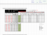
- The pad data is kept in the worksheet STORE that is visible to the user. Using spreadsheet features of Excel, new data can be generated and the existing one examined and or modified.
- The template has virtually no user interface. The printed Output matches the Screen Display. Knowing how to use Excel and the ability to verify results as a designer is sufficient for using EccPad.
- Green shaded cells in the spreadsheet signify User-Input and un-shaded cells signify Spreadsheet-Results. This permits easy checking at a glance by the users and the checkers of EccPad output.
Calculation Reference
Structural Engineering

