Since wide scale coal firing for power generation began in the1920s, many millions of tons of ash and related by-products have been generated. The current annual production of coal ash world-wide is estimated around 600 million tones, with fly ash constituting about 500 million tones at 75–80% of the total ash produced.
Thus, the amount of coal waste (fly ash), released by factories and thermal power plants has been increasing throughout the world, and the disposal of the large amount of fly ash has become a serious environmental problem. The present day utilization of ash on worldwide basis varied widely from a minimum of 3% to a maximum of 57%, yet the world average only amounts to 16% of the total ash.
Fly ash is generally grey in color, abrasive, mostly alkaline, and refractory in nature. Pozzolans, which are siliceous or siliceous and aluminous materials that together with water and calcium hydroxide form cementitious products at ambient temperatures,are also admixtures.
Fly ash from pulverized coal combustion is categorized as such a pozzolan. Fly ash also contains different essential elements, including both macro nutrients P, K, Ca, Mg and micro nutrients Zn, Fe, Cu, Mn, B, and Mo for plant growth. The geotechnical properties of fly ash (e.g., specific gravity, permeability,internal angular friction, and consolidation characteristics) make it suitable for use in construction of roads and embankments, structural fill etc.
The pozzolanic properties of the ash, including its lime binding capacity makes it useful for the manufacture of cement, building materials concrete and concrete-admixed products.
Fly Ash Types :
There are two common types of fly ash: Class F and Class C.
Class F fly ash contain particles covered in a kind of melted glass. This greatly reduces the risk of expansion due to sulfate attack, which may occur in fertilized soils or near coastal areas. Class F is generally low-calcium and has a carbon content less than 5 percent but sometimes as high as 10 percent.
Class C fly ash is also resistant to expansion from chemical attack. It has a higher percentage of calcium oxide than Class F and is more commonly used for structural concrete. Class C fly ash is typically composed of high-calcium fly ashes with a carbon content of less than 2 percent.
Currently, more than 50 percent of the concrete placed in the U.S. contains fly ash.2 Dosage rates vary depending on the type of fly ash and its reactivity level. Typically, Class F fly ash is used at dosages of 15 to 25 percent by mass of cementitious material, while Class C fly ash is used at dosages of 15 to 40 percent.3
Fly Ash Applications :
Utilization of fly ash appears to be technically feasible in the cement industry. There are essentially three applications for fly ash in cement
(1) replacement of cement in Portland cement concrete
(2) pozzolanic material in the production of pozzolanic cements
(3) set retardant ingredient with cement as a replacement of gypsum
Cement is the most cost and energy intensive component of concrete. The unit cost of concrete is reduced by partial replacement of cement with fly ash.
The utilization of fly ash is partly based on economic grounds as pozzolana for partial replacement of cement, and partly because of its beneficial effects, such as, lower water demand for similar workability, reduced bleeding, and lower evolution of heat.
It has been used particularly in mass concrete applications and large volume placement to control expansion due to heat of hydration and also helps in reducing cracking at early ages.
The major drawback of fibre reinforced concrete is its low workability. To overcome this shortcoming, a material is needed, which can improve the workability without comprising strength.
The use of fly ash in concrete enhances the workability of concrete and being widely recommended as partial replacement of cement. This also reduces the cost of construction. Fly ash concrete provides much strong and stable protective cover to the steel against natural weathering action.
The list of potential causes of concrete failures is a long one. A few examples include chemical reactions, shrinkage, weathering, and erosion. Many other potential causes exist, and we will explore them individually. Understanding the causes of concrete structure dam-age is an important element in the business of rehab and repair work.
1. UNINTENTIONAL LOADS
Unintentional loads are not common, which is why they are accidental. When an earth-quake occurs and affects concrete structures, that action is considered to be an accidental loading. This type of damage is generally short in duration and few and far between in occurrences.
Visual inspection will likely find spalling or cracking when accidental loadings occur. How is this type of damage stopped? Generally speaking, the damage cannot be prevented, because the causes are unexpected and difficult to anticipate. For example, an engineer is not expecting a ship to hit a piling for a bridge, but it happens. The only defense is to build with as much caution and anticipation as possible.
2. CHEMICAL REACTIONS
Concrete damage can occur when chemical reactions are present. It is surprising how little it takes for a chemical attack on concrete to do serious structural damage.
Examples of chemical reactions and how they affect concrete:
a- Acidic Reactions
Most people know that acid can have serious reactions with a number of materials, and concrete is no exception. When acid attacks concrete, it concentrates on its products of hydration. For example, calcium silicate hydrate can be adversely affected by exposure to acid.
Sulfuric acid works to weaken concrete and if it is able to reach the steel reinforcing members, the steel can be compromised. All of this contributes to a failing concrete structure.
Visual inspections may reveal a loss of cement paste and aggregate from the matrix. Cracking, spalling, and discoloration can be expected when acid deteriorates steel reinforcements, and laboratory analysis may be needed to identify the type of chemical causing the damage.
b- Aggressive Water
Aggressive water is water with a low concentration of dissolved minerals. Soft water is considered aggressive water and it will leach calcium from cement paste or aggregates. This is not common in the United States. When this type of attack occurs, however, it is a slow process. The danger is greater in flowing waters, because a fresh supply of aggressive water continually comes into contact with the concrete.
If you conduct a visual inspection and find rough concrete where the paste has been leached away, it could be an aggressive-water defect. Water can be tested to determine if water quality is such that it may be responsible for damage. When testing indicates that water may create problems prior to construction, a non-Portland-cement-based coating can be applied to the exposed concrete structures.
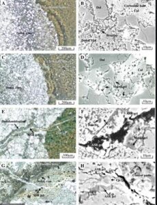
c- Alkali-Carbonate Rock Reaction
Alkali-carbonate rock reaction can result in damage to concrete, but it can also be beneficial. Our focus is on the destructive side of this action, which occurs when impure dolomitic aggregates exist. When this type of damage occurs, there is usually map or pattern cracking and the concrete can appear to be swelling.
Alkali-carbonate rock reaction differs from alkali-silica reaction because there is a lack of silica gel exudations at cracks. Petrographic examination can be used to confirm the presence of alkali-carbonate rock reaction. To prevent this type of problem, contractors should avoid using aggregates that are, or are suspected to be, reactive.
d- Alkali-Silica Reaction
An alkali-silica reaction can occur when aggregates containing silica that is soluble in highly alkaline solutions may react to form a solid, non expansive, calcium-alkali-silica complex or an alkali-silica complex that can absorb considerable amounts of water and expand. This can be disruptive to concrete.
Alkali-silica reaction in concrete
Concrete that shows map or pattern cracking and a general appearance of swelling could be a result of an alkali-silica reaction. This can be avoided by using concrete that contains less than 0.60% alkali.
e- Various Chemical Attacks
Concrete is fairly resistant to chemical attack. For a substantial chemical attack to have degrading effects of a measurable nature, a high concentration of chemical is required. Solid dry chemicals are rarely a risk to concrete. Chemicals that are circulated in contact with concrete do the most damage.
When concrete is subjected to aggressive solutions under positive differential pressure, the concrete is particularly vulnerable. The pressure can force aggressive solutions into the matrix. Any concentration of salt can create problems for concrete structures. Temperature plays a role in concrete destruction with some chemical attacks. Dense concrete that has a low water–cement ratio provides the greatest resistance.
The application of an approved coating is another potential option for avoiding various chemical attacks.
f- Sulfate Situations
A sulfate attack on concrete can occur from naturally occurring sulfates of sodium, potassium, calcium, or magnesium. These elements can be found in soil or in ground water. Sulfate ions in solution will attack concrete. Free calcium hydroxide reacts with sulfate to form calcium sulfate, also known as gypsum. When gypsum combines with hydrated calcium aluminate it forms calcium sulfoaluminate.
Either reaction can result in an increase in volume. Additionally, a purely physical phenomenon occurs where a growth of crystals of sulfate salts disrupts the concrete. Map and pattern cracking are signs of a sulfate attack. General disintegration of concrete is also a signal of the occurrence.Sulfate attacks can be prevented with the use of a dense, high-quality concrete that has a low water–cement ratio. A Type V or Type II cement is a good choice.
If pozzolan is used, a laboratory evaluation should be done to establish the expected improvement in performance.
g- Poor Workmanship
Poor workmanship accounts for a number of concrete issues. It is simple enough to follow proper procedures, but there are always times when good practices are not employed. The solution to poor workmanship is to prevent it. This is much easier said than done. All sorts of problems can occur when quality workmanship is not assured and some of the key causes for these problems are as noted below:
Adding too much water to concrete mixtures
Poor alignment of formwork
Improper consolidation
Improper curing
Improper location and installation of reinforcing steel members
Movement of formwork
Premature removal of shores or reshores
Settling of concrete
Settling of subgrade
Vibration of freshly placed concrete
Adding water to the surface of fresh concrete
Miscalculating the timing for finishing concrete
Adding a layer of concrete to an existing surface
Use of a tamper
Jointing
3. CORROSION
Corrosion of steel reinforcing members is a common cause of damage to concrete. Rust staining will often be present during a visual inspection if corrosion is at work. Cracks in concrete can tell a story. If they are running in straight lines, as parallel lines at uniform intervals that correspond with the spacing of steel reinforcement materials, corrosion is prob-ably at the root of the problem. In time, spalling will occur. Eventually, the reinforcing mate-rial will become exposed to a visual inspection.
Techniques for stopping, or controlling, corrosion include the use of concrete with low permeability. In addition, good workmanship is needed. Some tips to follow include:
Use as low a concrete slump as
Cure the concrete
Provide adequate concrete cover over reinforcing
Provide suitable
Limit chlorides in the concrete
Pay special attention to any protrusions, such as bolts and
4.FREEZING AND THAWING
Freezing and thawing during the curing of concrete is a serious concern. Each time the concrete freezes, it expands. Hydraulic structures are especially vulnerable to this type of damage. Fluctuating water levels and under-spraying conditions increase the risk. Using deicing chemicals can accelerate damage to concrete with resultant pitting and scaling. Core samples will probably be needed to assess damage.
Prevention is the best cure. Provide adequate drainage, where possible, and work with low water–cement ratio concrete. Use adequate entrained air to provide suitable air-void systems in the concrete. Select aggregates best suited for the application, and make sure that concrete cures properly.
5. SETTLEMENT AND MOVEMENT
Settlement and movement can be the result of differential movement or subsidence. Concrete is rigid and cannot stand much differential movement. When it occurs, stress cracks and spall are likely to occur. Subsidence causes entire structures or single elements of entire structures to move. If subsidence is occurring, the concern is not cracking or spalling; the big risk is stability against overturning or sliding.
A failure via subsidence is generally related to a faulty foundation. Long-term consolidations, new loading conditions, and related faults are contributors to subsidence. Geotechnical investigations are often needed when subsidence is evident.
Cracking, spalling, misaligned members, and water leakage are all evidence of structure movement. Specialists are normally needed for these types of investigations.
6. SHRINKAGE
Shrinkage is caused when concrete has a deficient moisture content. It can occur while the concrete is setting or after it is set. When this condition happens during setting, it is called plastic shrinkage; drying shrinkage happens after concrete has set.
Plastic shrinkage is associated with bleeding, which is the appearance of moisture on the surface of concrete. This is usually caused by the settling of heavier components in a mixture. Bleed water typically evaporates slowly from the surface of concrete.
Concrete Shrinkage
When evaporation occurs faster than water is supplied to the surface by bleeding, high-tensile stresses can develop. This stress can lead to cracks on the concrete surface.Cracks caused by plastic shrinkage usually occur within a few hours of concrete placement.
These cracks are normally isolated and tend to be wide and shallow. Pattern cracks are not generally caused by plastic shrinkage.
Weather conditions contribute to plastic shrinkage. If the conditions are expected to be conducive to plastic shrinkage, protect the pour site with windbreaks, tarps, and similar arrangements to prevent excessive evaporation. In the event that early cracks are discovered, revibration and refinishing can solve the immediate problem. Drying shrinkage is a long-term change in volume of concrete caused by the loss of moisture.
A combination of this shrinkage and restraints will cause tensile stresses and lead to cracking. The cracks will be fine and the absence of any indication of movement will exist. The cracks are typically shallow and only a few inches apart. Look for a blocky pattern to the cracks.
They can be confused with thermally induced deep cracking, which occurs when dimensional change is restrained in newly placed concrete by rigid foundations or by old lifts of concrete.
To reduce drying shrinkage, try the following precautions:
Use less water in
Use larger aggregate to minimize paste
Use a low temperature to cure concrete
Dampen the subgrade and the concrete
Dampen aggregate if it is dry and
Provide adequate
Provide adequate contraction joints
7. FLUCTUATIONS IN TEMPERATURE
Fluctuations in temperature can affect shrinkage. The heat of hydration of cement in large placements can present problems. Climatic conditions involving heat also affect concrete; for example, fire damage, while rare, can also contribute to problems associated with excessive heat.
What are the main types Of Grout Used In Construction
What Is Grout?
Grout is a thick paste that is used to fill gaps, voids, or joints. It is mainly a composite material used for grouting, repairing concrete cracks, filling gaps and sealing the joints between tiles, waterproofing, soil stabilization, etc.
In this article, I will discuss different types of grout materials used in construction, tile installation, and other works. Differing from mortar, grout has a low viscosity and lack of lime, which makes it thinner and easier to work with.
Types Of Grout:
1. Cementitious Grout:
Cementitious grouts are the traditional grouting material, used both in residential as well as some commercial applications. It is also known as slurry grouting or hydraulic cement grouting. Materials used in cementitious grout are :
Portland cement,
Filler particles of different sizes,
Water-retentive additive,
Colored pigments.
Cementitious grouts are available in a variety of colors that let you match or contrast with the tile. Water is mixed with the grout and then applied using a trowel. The water retentive ingredient in cementitious grouts slows down the drying time, allowing the cement to cure slowly achieving maximum hardness.
Cementitious grouts are further classified into three types:
Sanded grout
Unsanded /Non-sanded grout
Latex modified grout.
a. Sanded Grout:
Sanded grout is composed of portland cement, sand, and other additives. The sand used is relatively larger in size. It is typically recommended for tile floors where joints are 1/8 inch to 3/8 inch wide. Sand provides extra strength to the grout joints, as it is one of the best building materials.
Sanded grout is absorbent and easily attracts dirt, therefore it is always better to seal the joint when grouting is done. As sand easily makes scratches, this type of grout should not be used on easily scratched tile like marble.
Sanded tile grout is less costly than unsanded grout because sand is a cheaper filler than polymers. It also provides a tight lock and a neat & clean finish.
Sanded grouts are ideal for use in Kitchen floor Bathroom floor Entryways Shower pan etc.
b. Unsanded Grout:
Unsanded grout is made of portland cement and color powder pigments. No sand is used here hence also known as non-sanded grout.
This type of grout is suitable for joint thickness between 1/8 to 1/16 inches. Unlike sanded grout, it is useful in scratchable surfaces such as metal, glass, marble, and natural stone tile.
Unsanded grout provides a much smoother texture since the mineral particles present in it are very fine powders without having grit. However, these grouts easily develop cracks due to lack of binding power.
Unsanded grout is costly than sanded and you may have limited color options. Unsanded grouts are suitable for use in Rectified tiles, Polished stones. Bathroom walls, Shower walls etc.
c. Latex Modified Grout:
Sanded grouts may be composed of a latex polymer additive which increases the strength and water-proofing properties of grout. The additives can be mixed in both dry and wet conditions.
2. Chemical Grouts:
Chemical grouts consist of polymers such as epoxy, acrylic, polyurethane, sodium silicate, or any other suitable polymer. It requires injection of chemical grouts into finer cracks that are not groutable by cementitious grouts. Some useful types of chemical grouts are discussed below.
a. Epoxy Grout:
Epoxy grout is consists of epoxy resin, silica fillers, pigments, and a hardener. It neither uses Portland cement nor uses water during the mixing process.
Epoxy grout is very strong and durable. Additionally, it is highly resistant to stains, cracks, chemicals attack, harsh weather conditions, and climatic changes.
Epoxy grouts are considerably less porous than cementitious grouts and set up quickly. It is also much costlier than any other type of grout. With light maintenance, epoxy grout can last lifelong if applied correctly.
The strength and other properties make it perfect for any tile work, indoors or outdoors. It is suitable for use in High traffic areas like entryways, hallways, and foyers.
Any type of flooring exposed to harsh conditions like grease and acid. Kitchen counters and backsplash, bathrooms, etc. Keep in mind, porous and unglazed surfaces, such as limestone or quarry tiles need to be sealed before applying epoxy grout, otherwise, it can stain the tile surfaces badly.
Another major disadvantage that it is much more difficult to shape and slope. If not done correctly, it will look plastic.
b. Furan Grout:
Furan grout is similar to epoxy but composed of polymers of fortified alcohols. There is no water used in this type of grout installation. Furan is basically a combination of furan resin and a filler powder with an acid catalyst.
The acid catalyst helps the resin to cure making it a thermosetting resin that has unsurpassed chemical, physical, and thermal resistance.
The tile surfaces may be smooth, abrasive or non-skid hence it should be sealed with wax coating right after furan grout installation to protect from staining. Furan grout is the strongest and most expensive grout material available in the market.
Because of the difficulty of installation, it requires proper precautions and skilled labours. This type of grout is suitable for use in Brick pavers, Quarry tiles. Industrial projects, such as laboratories, factories, dairies, and meat-packing plants. Areas highly exposed to chemicals and/or grease.
c. Acrylic Grout:
Acrylic grout is an acrylic latex admixture composed for use as a substitute for water when grouting ceramic tile. It is specifically produced for use with AccuColor Portland cement grouts. Acrylic grout helps to make joints less susceptible to water penetration.
It is very much essential when grouting wet areas. The additive further helps the grout retaining its color and resisting stains. It gives good stability in freezes and thaws. It also enhances grout flexibility. It has greater adhesion properties. Additionally, you don’t need to cover the entire work surface.
You can just apply it in between tile joints. Another advantage of using acrylic latex grout is that it can be used in small spaces. It is mostly suitable for joint thickness less than 1/8 inch. This type of grout is especially suitable for use in Outdoors such as deck or garage projects. Fast-food restaurant floors. Marble work etc.
A culvert is a covered channel of relatively short length designed to pass water through an embankment (e.g. highway, railroad and dam).
It is a hydraulic structure and it may carry flood waters, drainage flows, natural streams below earthfill and rockfill structures. From a hydraulic aspect, a dominant feature of a culvert is whether it runs full or not.
The design can vary from a simple geometry (i.e. box culvert) to a hydraulically smooth shape (i.e. minimum energy loss (MEL) culvert)
Culvert Parts :
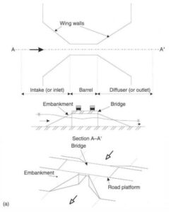
A culvert consists of three parts: the intake (also called inlet or fan), the barrel (or throat) and the diffuser (also called outlet or expansion fan) (Fig.1-a).
The cross-sectional shape of the barrel may be circular (i.e. pipe), rectangular (i.e box culvert) or multi-cell (e.g. multi-cell box culvert) (Fig.1-b).
The bottom of the barrel is called the invert while the barrel roof is called the soffit or obvert. The training walls of the inlet and outlet are called wing walls.
Fig 1. Sketch of a culvert: (a) box culvert
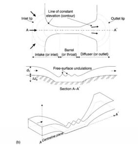
Fig 1. (b) MEL culvert
Standard Culverts :
A standard culvert is designed to pass waters at a minimum cost without much consideration of the head loss. The culvert construction must be simple: e.g. circular pipes and precast concrete boxes.
MEL Culverts :
An MEL culvert is a structure designed with the concept of minimum head loss. The flow in the approach channel is contracted through a streamlined inlet into the barrel where the channel width is minimum, and then it is expanded in a streamlined outlet before being finally released into the downstream natural channel. Both the inlet and outlet must be streamlined to avoid significant form losses
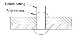
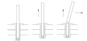
Rivets are non threaded fasteners that are usually manufactured from steel or aluminium. They consist of a preformed head and shank, which is inserted into the material tobe joined and the second head that enables the rivet to function as a fastener is formedon the free end by a variety of means known as setting.
A conventional rivet before and after setting is illustrated in Fig. 1.
Fig.1 Conventional rivet before and after setting
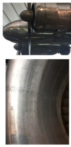
Rivets are widely used to join components in aircraft (e.g. see Fig.2) boilers, ships and boxes and other enclosures. Rivets tend to be much cheaper to install than bolts and the process can be readily automated with single riveting machines capable of installing thousands of rivets an hour.
Fig 2. Two historical examples of the use of rivets on the Lockheed Electra and RB211engine nacelle.
Rivets can be made from any ductile material such as carbon steel, aluminium and brass. A variety of coatings are available to improve corrosion resistance. Care needs to be taken in the selection of material and coating to avoid the possibility of corrosion by galvanic action.
In general a given size rivet will be not as strong as the equivalent threaded fastener.
The two main types of rivet are tubular and blind and each type are available in amultitude of varieties. The advantage of blind rivets (Fig.3) is that they require access to only one side of the joint.
Fig 3. An example of the application of a closed end blind rivet
A further type of rivet with potentially many over-all advantages, from the production perspective, is the self-piercing rivet that does not require a predrilled hole. The rivet is driven into the target materials with high force, piercing the top sheets and spreading outwards into the bottom sheet of material under the influence of an upsetting die to form the joint.
Factors in the design and specification of rivets include the size, type and material for the rivet, the type of joint, and the spacing between rivets.
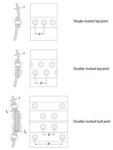
There are two main types of riveted joint: lap-joints and butt-joints(Fig.4).
In lap joints the components to be joined overlap each other, while for butt joints an additional piece of material is used to bridge the two components to be joined which are butted up against each other.
Rivets can fail by shearing through one cross-section known as single shear, shearing through two cross-sections known as double shear, and crushing. Riveted plates can fail by shearing, tearing and crushing.
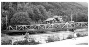
A truss is a special type of structure renowned for its high strength- to- weight and stiffness- to- weight ratios.
This structural form has been employed for centuries by designers in a myriad of applications ranging from bridges and race car frames to the International Space Station.Trusses are easy to recognize: lots of straight slender struts joined end- to- end to form a lattice of triangles, such as the bridge in Fig.1.
Fig.1 Truss bridge in Interlaken, Switzerland
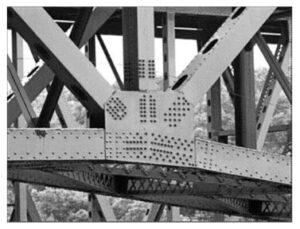
In large structures, the joints are often created by riveting the strut ends to a gusset plate as shown in Fig.2.
A structure will behave like a truss only in those regions where the structure is fully triangulated; locations where the struts form other polygonal shapes (e.g., a rectangle) may be subject to a loss of stiffness and strength.
Fig.2 Joint formed by riveting a gusset plate to converging members
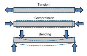
The special properties of a truss can be explained in terms of the loads being applied to the individual struts. Consider the three general types of end loadings shown in Fig.3 tension, compression, and bending.
If you were holding the ends of a long thin steel rod in your hands and wanted to break it or at least visibly deform it, bending would be the way to go. Thus, if we could eliminate bending of the struts as a potential failure mode, the overall strength and stiffness of the truss would be enhanced.
Fig.3 Different end loading possibilities. The dashed represents the deformed shape produced by the applied forces
This is precisely the effect of the truss geometry on the structure, as the stiff triangular lattice serves to keep any bending induced in the struts to a minimum.
High-performance concrete may be defined as concrete with strength and durability significantly beyond those obtained by normal means. The required properties for concrete to be classiffied as high performance therefore depend on the properties of normal concrete achievable at a particular time and location.
At the present time, high-performance concrete in developed countries usually refers to concrete with 28-day compressive strength beyond 70±80 MPa, durability factor (defined as the percentage of original modulus retained after 300 freeze/thaw cycles) above 80%, and w/c below 0.35.
It is made with good quality aggregates, high cement content (450±550 kg mw-3), and a high dosage of both silica fume (5±15 wt.% of cement) and super plasticizer (5±15 l mw-3). Sometimes other pozzo-lanic materials are also used.
The high performance is achieved with the use of low w/c (0.20±0.35) as well as pozzolans to produce a dense microstructure that is high in strength and low in permeability.
Superplasticizer is added to keep the mix workable.With high cement content, the use of super-pasticizers and silica fume and the need for more stringent quality control the unit cost of high-performance concrete can exceed that of normal concrete by 30±100%.
2. When High Performance Concrete is Used:
Despite the higher material cost, the use of high-performance concrete is found to be economical for columns of tall buildings, as the amount of steel reinforcement can be reduced.
In bridges, the reduction in deck size and weight effectively increases the allowable unsupported span. For a continuous bridge, the number of piers can be reduced. In many infrastructure projects, high-performance concrete is chosen for its durability against various types of chemical (e.g., sulfate or chloride) and physical attack (e.g., abrasion).
High-performance concrete can also be produced with lightweight aggregates. However, the aggregate needs to be very carefully chosen to make sure it is sufficiently strong. As long as the light weight aggregateis strong enough, its use can indeed be advantageous.
By saturating their pores with water before mixing, these aggregates can act as internal reservoirs that supply water to ensure continued cement hydration and prevent auto geneous shrinkage due to self-desiccation. This aspect is of particular relevance to concrete with a very low w/c, in which the early development of high density and low permeability makes it difficult for water to penetrate uniformly forthe hydration process to continue.
Besides the production of high-performance concrete, superplasticizers are also commonly used in the production of high-workability concrete. With aslump value of 180±230 mm, high-workability concrete can be pumped rapidly over long distances, easily compacted in structures with highly congested re-inforcement, and can even be self-compacting (i.e.,requiring no external compaction effort).
With super-plasticizers, it is also possible to reduce the cement content while retaining the same workability. The possibility of thermal cracking in massive structures can therefore be reduced.
In the continual quest for improving concrete performance, it was soon realized that the size of aggregates is an important factor. By using very fine aggregates, superplasticizers, and a high dose of silica fume (about 20±30% of the cement content) concrete strength beyond 200 MPa can now be achieved by conventional techniques. One example is DSP–densified system with fine particles.
Using strongaggregates of small size (e.g., calcined bauxite withmaximum size of 4 mm), DSP with compressive strength over 250 MPa can be produced.
Reaction powder concrete (RPC) is another example. With the maximum particle size limited to 0.4 mm, the compressive strength reaches 170 MPa by 28 days under room temperature curing. Curing at 80±90∞C will further increase the strength to 230 MPa. If pressure is applied before and during setting, and curing is carriedout at 400∞C, strength as high as 680 MPa can be attained. With very high strength, both DSP and RP Care extremely brittle. Fiber reinforcement is therefore essential to prevent catastrophic failure at ultimateload.
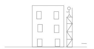
During construction, temporary structures are required. Let us assume a simple task of painting a building. How could workers go up to the upper levels to paint? Typically, workers stand on a temporary structure known as a scaffold (Fig.1).
Fig.1. The painting of a building. A scaffold is built for painters to stand on while painting the building
1. SCAFFOLDS
Scaffolds are work platforms that enable workers to do their job at high elevations. The type of work can be brickwork, painting, steel work, concreting, or window installation. Most scaffolds are made of steel pipes. In some countries bamboo is stillused for scaffolds.
1.1 Pipe Scaffolds
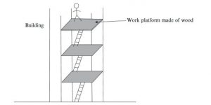
Pipes are used to build scaffolds. Pipes are connected using special connectors. Platforms are provided for workers to stand on. Ladders are provided for workers to go from one platform to another one (Figs.2 and 3). Pipe scaffolds cannot be used for very tall buildings. Other methods such as outrigger scaffolds are used in such situations.
Fig.2. Pipe scaffold with one platform
Fig.3. Pipe scaffold with multiple platforms. Ladders are provided to climb to higher platforms
1.2 Outrigger Scaffolds
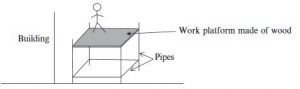
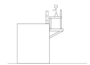
Consider this scenario: Brickwork has to be done on the 70th story of a 70-story building. How could the workers get to the 70th story? Should they build a pipe scaffold from the ground all the way to the 70th story? That may not be very feasible. In this type of situation, outrigger scaffolds can be used. Metal beams are attached to the building. These beams are used to build a work platform (Fig.4).
In the case of outrigger scaffolds, metal beams or a metal structure are attached to the newly constructed building. This has to be done with the authorization of design engineers. This metal structure is known as outriggers. The protruding metal structure is used to build a work platform.
Fig.4. Outrigger scaffold
1.3 Modular Scaffolds
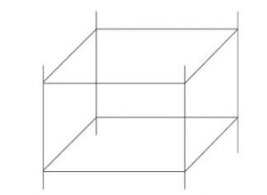
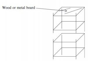
Pre-made modules are becoming common in many construction projects (Figs.5 and 6).
Fig.5. Scaffolding modules
Fig.6. Scaffolding modules are fitted together to reach high elevations
Boards: Boards are made of metal or wooden planks attached to the scaffolding for people to stand and work. Uprights also known as standards and poles are used to carry the load to base. False uprights are mainly used near entrances to the work platform. False uprights do not transfer any vertical loads to the ground. Though it may provide lateral support handrails, it does not provide any lateral supports to the scaffold system.
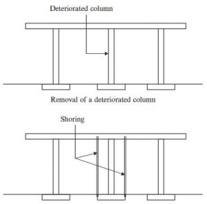
2. SHORING
Scaffolds are built for workers to work. Scaffolds act as work platforms for workers. On the other hand, shoring is done to support wet concrete. Once the concrete is hardened, the shoring is removed. Other than supporting wet concrete, shoring can be used to support weak columns.Let us assume that an existing column in a building is deteriorated and has to be replaced. The procedure to remove an existing column and build a new column is shown in Fig.7.
Fig.7. Provide shoring prior to removal of the column
Once proper shoring is provided and has been approved by the relevant authorities, the contractor can remove the existing load bearing column and construct a new one.
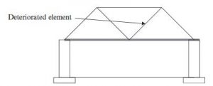
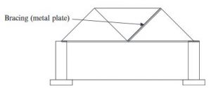
3. BRACING
Bracing is a support element provided to strengthen an existing structural element (Figs.8 and 9).
Fig.8. Deteriorated element in a structure
Fig.9. Bracing is provided for the deteriorated element
3.1 Bracing Masonry Walls
Masonry walls need to be braced during and after construction. All masonry walls have to be supported laterally. In a building, masonry walls are tied to beams, columns, and other walls.
Until the masonry wall is laterally supported, it has to be braced. In practice, bracing of masonry walls has to follow OSHA guidelines. For the exam purposes, NCEES recommends “Standard Practice for Bracing Masonry Walls Under Construction” by Mason Contractors Association of America (MCAA).
Hence, you need to know both OSHA and MCAA guidelines (Fig.10). Masonry walls are made of bricks and mortar. Until a mortar brick joint is fully developed, masonry walls have little lateral stability.
Even after the mortar is hardened, a standing masonry wall has little resistance against over-turning. As per OSHA, any wall 8 ft or taller needs to be braced.
Fig.10. Schematic diagram of a masonry wall bracing. Bracing is required tomaintain the lateral stability of a masonry wall
4. COFFERDAMS
There are instances where construction has to take place near a river, lake, or ocean. Bridge piers, harbor structures, and flood control structures are some examples. In such situations water has to be kept away from the construction area.
How can you concrete when water is pouring in? A structure has to be built to keep the water away. In such situations a temporary structure needs to be constructed to keep the water away. These temporary structures are known as cofferdams.
Cofferdams are temporary structures constructed to keep water out ofthe construction area. The majority of cofferdams are constructed in riversmainly to build bridge piers. Thanks to improvement in caisson technology, in most cases cofferdams may not be necessary anymore.
Once a plant is in operation it is important to monitor the progress of any corrosion which might be taking place. The four approaches described below vary in sophistication and cost.
The most appropriate for any plant is determined by a number of factors, including the mechanisms of corrosion which are anticipated and the implications of catastrophic or unexpected failure. Key areas of the plant require closer monitoring than readily replaceable items.
The measures described below do not replace the mandatory inspections of pressure vessels, etc. for insurance purposes. The overall philosophy of corrosion monitoring is to improve the economics of the plant’s operation by allowing the use of cheaper materials and generally reducing the over-design that goes into plant to combat corrosion.
1. Physical examination
Full records of all constructional materials that are used in the plant should be maintained and updated when repairs are undertaken.
The exteriors of all parts of the plant should be subjected to frequent visual examination and the results reported and stored for future reference. This maximizes the warning time before corrosion failures occur, since the majority of failure mechanisms cause leaks before bursting.
Key items of plant, those in which some degree of corrosion is anticipated and those which might suffer catastrophic failure should be examined in greater detail. Internal visual inspection during shutdowns is sufficient to identify most corrosion effects.
Cracking can usually be seen with the naked eye but where cracking is considered to be a possible mechanism an appropriate non-destructive test method should be employed. In items of plant which are shut down only infrequently (relative to the timescale of possible corrosion or cracking failure) external non-destructive testing is often possible.
Candidate non-destructive test methods include:
a. Ultrasonic techniques:
Wall thickness can be mea- sured to monitor the progress of general corrosion, cracks can be detected and hydrogen blisters identified. Certain construction materials such as cast iron cannot be examined by ultrasound. Skilled operators and spe- cialist equipment is required. Plant can be examined in situ except when it is above 80°C.
b. Magnetic particle inspection:
Surface emergent and some sub-surface cracking can be detected in ferro- magnetic materials. The technique must be used on the side of the material in contact with the corrodent.
c. Dye penetration inspection:
This is a simple technique, requiring a minimum of operator training. In the hands of a skilled operator it is capable of detecting fine cracks such as chloride stress corrosion cracks in austenitic stainless steels and fatigue cracks.
2. Exposure coupons and electrical resistance probes
If changes have been made to the process (e.g. if incoming water quality cannot be maintained or other uncertainties arise) concerning the corrosion behaviour of the construction materials, it is possible to incorporate coupons or probes of the material into the plant and monitor their corrosion behaviour.
This approach may be used to assist in the materials selection process for a replacement plant. Small coupons (typically, 25 × 50mm) of any material may be suspended in the process stream and removed at intervals for weight loss determination and visual inspection for localized corrosion.
Electrical resistance probes comprise short strands of the appropriate material electrically isolated from the item of plant. An electrical connection from each end of the probe is fed out of the plant to a control box. Instrumentation in the box senses the electrical resistance of the probe.
The probe’s resistance rises as its cross-sectional area is lost through corrosion. The materials should be in the appropriate form, i.e. cast/wrought/welded, heat treatment and surface condi- tion.
Metal coupons should be electrically isolated from any other metallic material in the system. They should be securely attached to prevent their being dislodged and causing damage downstream.
Simple coupons and probes cannot replicate the corrosion effects due to heat transfer but otherwise provide very useful information. It should be noted that any corrosion they have suffered represents the integrated corrosion rate over the exposure time.
Corrosion rates often diminish with time as scaling or filming takes place, thus short-term exposures can give values higher than the true corrosion rate.
3. Electrochemical corrosion monitoring
A number of corrosion-monitoring techniques, based on electrochemical principles, are available. These give an indication of the instantaneous corrosion rate, which is of use when changing process conditions create a variety of corrosion effects at different times in a plant. Some techniques monitor continuously, others take a finite time to make a measurement.
Polarization resistance: The current-potential behaviour of a metal, externally polarized around its corrosion potential, provides a good indication of its corrosion
The technique has the advantage of being well established and hence reliable when used within certain limitations.
This technique can only be used for certain metals, to give general corrosion rate date in electrolytes. It cannot be employed to monitor localized corrosion such as pitting, crevice corrosion or stress corrosion cracking, nor used in low-conductivity environments such as concrete, timber, soil and poor electrolytes (e.g. clean water and non-ionic solvents). Equipment is available commercially but professional advice should be sought for system design and location of probes.
Impedance spectroscopy: This technique is essentially the extension of polarization resistance measurements into low-conductivity environments, including those listed
The technique can also be used to monitor atmospheric corrosion, corrosion under thin films of condensed liquid and the breakdown of protective paint coatings. Additionally, the method provides mechanistic data concerning the corrosion processes which are taking place
Electrochemical noise: A variety of related techniques are now available to monitor localized No external polarization of the corroding metal is required, but the electrical noise on the corrosion potential of the metal is monitored and analysed. Signatures characteristic of pit initiation, crevice corrosion and some forms of stress corrosion cracking are obtained.
4. Thin-layer activation
This technique is based upon the detection of corrosion products, in the form of dissolved metal ions, in the process stream.
A thin layer of radioactive material is created on the process side of an item of plant. As corrosion occurs, radioactive isotopes of the elements in the construction material of the plant pass into the process stream and are detected.
The rate of metal loss is quantified and local rates of corrosion are inferred. This monitoring technique is not yet in widespread use but it has been proven in several industries.