Compaction test is conducted in the laboratory to determine the relation between the dry density and the water content of the given soil compacted with standard compaction energy and to determine the OMC corresponding to the MDD.
The OMC obtained from the laboratory compaction test will help in deciding the amount of water to be used for compaction in the field. The MDD obtained from the laboratory compaction test helps in knowing the dry density achievable in the field compaction and also as a check for quality control.
Based on the compacted energy used in compacting the soil in the laboratory test, the laboratory compaction tests are of two types:
1. Standard Proctor test.
2. Modified Proctor test.
1. Standard Proctor Test:
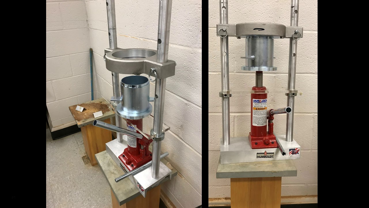
In this test, the soil is compacted in three layers, each layer subjected to blows of a rammer with falling weight of 5.5 pounds (2.6 kgf) falling through a height of 12 in. in a cylindrical mold of internal diameter of 4 in. and effective height of 4.6 in.
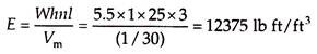
The compaction parameters in a standard Proctor test are – W is the weight of rammer blow = 5.5 pounds, h is the height of fall = 12 in. = 1 ft, n is the number of blows per layer = 25, l is the number of layers = 3, and Vm is the volume of the mold = 1/30 cubic ft. The total compaction energy imparted on the soil per unit volume in this test is –
IS – 2720 (Part 7) – 1980 recommends the Indian Standard light compaction method based on standard Proctor test in metric system. The standard Proctor test or IS light compaction can be used as a criteria for the compaction of subgrades on highways and earth dams, where light rollers are used.
2.Modified Proctor Test:
Advances in construction technology resulted in the development of heavier rollers, which impart higher compaction energy during field compaction. To provide a laboratory control criterion for the higher compaction energy, the modified Proctor test was developed and standardized by the American Association of State Highway (and Transportation) Officials (AASHO or AASHTO) and by US Army Corps of Engineers for airfield construction.
In modified Proctor test, the soil is compacted in the same mold as in standard Proctor test, which has internal diameter of 4 in. and affective height of 4.6 in. giving a total internal volume of 57.805 cubic in. or 1/30 cubic ft. The rammer is bigger with a hammer of weight 10 pounds (4.5 kgf) falling through a height of 18 in. The soil is compacted in five layers, each layer being given 25 blows.
The compaction parameters in modified Proctor test are as follows – W is the weight of hammer blow = 10 pounds, h is the height of fall = 18 in. = 1.5 ft, n is the number of blows per layer = 25,l is the number of layers = 5, and Vm is the volume of the mold = 1/30 cubic ft.
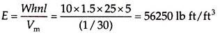
The compaction energy imparted to the soil, per unit volume, in the modified Proctor test is:
Thus, the compaction energy in the modified Proctor test is (56250/12375) 4.55 times that in standard Proctor test.
If the soil fraction retained on 20 mm sieve is more than 5%, a bigger mold of 5.9 in. (15 cm) internal diameter and 5 in. (12.73 cm) internal height giving a total volume of 137.04 cubic in. or 1/12.611 cubic ft (2250 cm3) is used. When the bigger mold is used, the soil is compacted with 56 blows for each layer.
IS – 2720 (Part VII) – 1980 and Part VIII-1983 have recommended procedures corresponding to these two tests as follows:
1. IS light compaction test.
2. IS heavy compaction test.
1. IS Light Compaction Test:
The objective of the IS light compaction test is to determine the relation between the water content and the dry density of compacted soil and to determine the MDD and OMC from this test. The compaction energy used to compact the soil corresponds to that of standard Proctor test.
The compaction parameters in IS light compaction test are as follows – W is the weight of hammer blow = 2.6 kgf, h is the height of fall = 31 cm, n is the number of blows per layer = 25, and I is the number of layers = 3, and Vm is the volume of the mold = 1000 cubic centimeter (cc). The total compaction energy imparted on the soil in this test is –
E = Whnl = 2.6 × 31 × 25 × 3 = 6045 kgf cm
The total compaction energy imparted on the soil per unit volume in this test is –
E = 6045/1000 = 6.045 kgf cm/cm3
2. IS Heavy Compaction Test:
The IS heavy compaction test is similar to IS light compaction text except for the following differences:
1. A heavy rammer of 4.9 kgf falling weight that falls through a height of 45 cm is used for compacting the soil in IS heavy compaction.
2. The soil is compacted in five layers of equal thickness in the compaction mold.
3. The initial water content to be used in the first trial is 3%-5% for sandy and gravelly soils and 12%-16% below plastic limit for cohesive soils.
To increase the accuracy of the test results, it is desirable to reduce the increment of water in the region of OMC.
Shifting and tilting problems occurs generally during sinking process of well foundations. If proper care is not taken, they will cause serious problems and weaken the stability of foundations. Precautions to avoid shifting and tilting, limitations and rectifying methods are discussed below.
Shifting and Tilting of Well Foundations
When the well is moved away horizontally from the desired position, then it is called shifting of well foundation.
When the well is sloped against vertical alignment,it is called tilting of well foundation.
Precautions to Prevent Shifting and Tilting
It is safer and economical to avoid tilting and shifting of wells by adopting the following preventive measures:
The outer surface of the well curb and steining should be level, straight, and smooth.
The radius of the well curb should be kept 2-4 cm more than the outer radius of the well steining.
The cutting edge should be sharp and of uniform thickness.
The steining should be built in lifts and the entire steining height should be built in one straight line from bottom to top at right angles to the plane of the curb.
Dredging should be uniform on all sides of the well. For a twin well, dredging should be uniform in both the wells.
The well should be constructed in stages of small height increments.
The magnitude and direction of sinking of wells should be properly and carefully monitored on a continuous basis to identify any tilt or shift and adopt appropriate corrective measures immediately to rectify the same.
If the well shows a tendency for tilting, dredging should be done on the higher side. If this does not bring required improvement, sinking should be stopped and should be resumed only after the tilting is corrected.
Dredged material should not be deposited unevenly around the well.
When a kentledge is used to provide additional sinking effort, it should be placed evenly on the loading platform.
Limitations
The maximum tilt allowed in case of well foundation is 1 in 60.
The shift in well foundation should not be more than 1 % of depth of sunk.
Beyond the above limits, well foundation is considered as dangerous and in such a case, remedial measures to rectify shifting and tilting should be followed.
Rectifying Methods
Rectifying methods for Rectification of shifting and tilting problems in well foundations are as follows:
Eccentric loading
Excavation on higher side
Water jetting
Pulling the well
Using hydraulic jacks
Using struts
Excavation under cutting edge
Wood sleeper under cutting edge
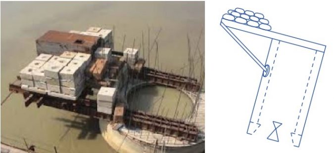
1. Eccentric loading
The well tilt can be rectified by placing eccentric loading on the higher side. Higher side is nothing but the opposite side of tilt or lower side.
A loading platform is constructed on the higher side and load is placed on it.
This eccentric load will increase downward pressure on higher side and correct the tilt.
The amount of load and eccentricity is decided based on the depth of sinking.
Greater is the depth of sinking of well, larger will be the eccentricity and load.
Fig 1: Eccentric Loading on Well Foundation
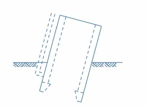
2. Excavation on Higher Side
When well is tilted to one side, excavation should be increased on the other side which is opposite to tilted side.
This technique is useful only in the initial stages of well sinking.
Fig 2: Excavation on Higher Side
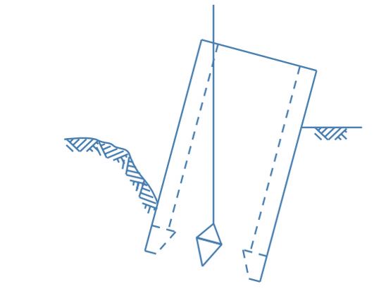
3. Water Jetting
Water jetting on external surface of well on the higher side is another remedial measure for rectifying tilt.
When water jet is forced towards surface of well, the friction between soil and well surface gets reduced and the higher side of well becomes lowered to make well vertical.
Fig 3: Water Jetting on Higher Side
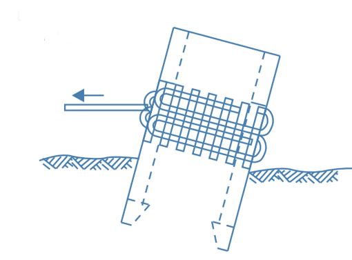
4. Pulling the Well
The well can be pulled towards higher side using steel ropes.
One or more steel ropes are wound around the well with wooden sleepers packed in between well and ropes to prevent damage to the well steining by distributing load over to larger area of steining.
Pull should be carefully done otherwise,shifting of well foundation may occur.
Fig 4: Pulling the Well Foundation
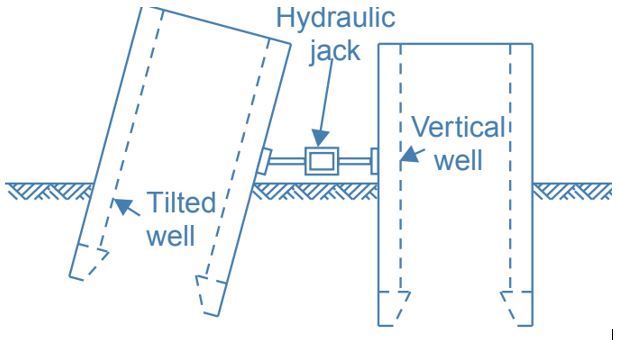
5. Pushing using Jacks
Another method to rectify tilting and shifting of well foundation is using hydraulic jacks or mechanical jacks, the tilted well can be pushed from lower side to higher side.
Neighbor vertical well foundations or suitable arrangements made will give support to the jack system.
Care should be taken while pushing the well otherwise the well may shifts.
Fig 5: Pushing using Jacks
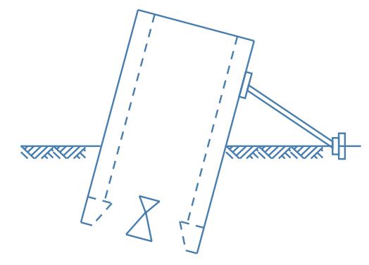
6. Using Struts
By providing struts as supports on the lower side or tilted side of well, further tilting can be prevented.
Wooden sleepers are provided between struts and well steining to prevent damage to well steining and to distribute pressure to larger area.
Struts are rested on firm base having driven piles.
Fig 6: Strutting the Well From Lower Side
7. Excavation under Cutting Edge
This technique is used for hard strata soils. In this method, the well is de-watered first and open excavation is carried out exactly under the cutting edge on the higher side.
If de-watering is not possible, soil strata is loosened using suitable equipment with the help of professional divers.
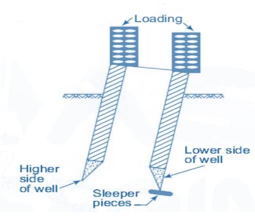
8. Wood Sleeper under Cutting Edge
If tilting towards lower side is increasing,then wooden sleepers are placed under cutting edge on lower side to control the tilting temporarily.
When well is corrected to vertical level, this sleepers can be removed.
Soil stabilisation, in terms of pavement construction, is the process of (usually insitu) pulverising and moisture conditioning by mixing various binders with soil, compaction and trimming as necessary. This improves soil characteristics preferred for construction in terms of moisture content, density, strength (CBR%), permeability, plasticity index and shrink swell characteristics. Most material types, clay through to crushed rock, are suitable for stabilisation. Seeking advice early during the design/feasibility stage enables planning for efficient use of stabilisation.
Stabilisation
Lime and/or cement stabilisation is often used to improve the properties of site won materials, to enable their use in a pavement and other like areas, such as dam foundations and building pad sites. Lime stabilisation of clay material reduces entrance cracking, whilst increasing the hardness of the material by up to ten times. The use of cement as a binder, after lime, can further increase the strength and durability towards that of concrete. Various binder blends, away from lime and cement, such as slag or fly ash, are commonly utilised for further benefit dependant on site conditions and requirements.
General Benefits of Soil Stabilisation
Saturated, wet sites can be treated to provide a working platform within a day for project continuation during wet periods/seasons.
Stabilisation recycles existing pavement by pulverising the existing pavement to 25mm down. Lime and or cement or other binders are then mixed with water as necessary. No imported materials and increased production rates means cost savings.
Strength gains often over CBR 15% or 5 times the previous strength are the result of the realignment of particles and adjustment of moisture content allowing compaction at optimum moisture content.
Reduce Plasticity Index (PI) in cohesive materials. For example a material with PI 20 will typically stabilise to PI < 10, say 8.
General Stabilisation for Lining Systems and Cohesive Expansion Material
Reduce or eliminate the need for imported clay liner by stabilising insitu materials.
Reduce permeability.
Reduce Linear Shrinkage rate up to 10%.
Environmental benefits of reduced geotextile, borrow pit clay and quarry import.
Additional environmental benefits from reducing extra excavation and disposal by modification to suitable material.
Improved structural stability through realignment of soil particles by ionic exchange between clay and lime.
Increased Strength and durability.
Reduced dispersion means reduced dispersion piping failure and increased erosion protection.
Pulverisation to 40mm down of clay, extremely weathered limestone, mudstone and siltstone provides smaller diameter conglomerates and homogenous material throughout the stabilised layer eliminating lenses, streaks, rock fissures and faults providing reduced seepage.
Lime
Note that there are many variations of lime available but only quicklime is considered suitable for lime stabilisation in the pavement construction industry and general field construction activities. Quicklime is calcium oxide (CaO) supplied commercially in a dry powder form. Agriculture Lime is a calcium carbonate (CaC03) and not suitable for pavement construction. Hydrated Lime is calcium hydroxide (Ca(OH)2) often used in the laboratory for lime saturation testing, not generally used on site for pavement construction.
Hydrated lime (calcium hydroxide), is produced by reacting water with quicklime (calcium oxide). CaO + H2O => Ca(OH)2. When calculated using the atomic weights, this converts practically to 5t Quicklime + 3t Water => 7t Hydrated lime + 1t Water Evapouration.
The pozzolanic reaction between lime with water and the silica and alumina in clay results in an ionic exchange, which permanently realigns the clay particles forming friable conglomerates. The new alignment of the particles provides less ability for the clay to absorb water around the particles. This makes the clay more waterproof, less expansive and therefore reduces the plasticity and linear shrinkage. The PI is often more than ½ and the shrinkage is often 10% of what it was. Practically this results in improved permeability less shrinkage cracking providing less chance of piping failure and seepage.
In a lime saturated environment (typically 3% to 4% quicklime), the clay-alumina and clay-silica become available to react with the free calcium to form calcium aluminates or silicates. The pozzolanic reaction is illustrated by the following equations:
Insitu stabilisation procedures vary depending upon the type of project and the binder used. All machinery suitable for the process is purpose built for stabilisation. A range of purpose built equipment has been developed according to specific requirements of various site conditions and design specifications for the process to be effective. Adaptation of agricultural equipment and other equipment does not meet specification requirements and results in a process failure.
Preparation
Prior to stabilisation commencing it is important to ensure the surface is prepared for stabilisation ahead of stabilisation. Preparation of a surface for stabilisation includes pegging out for stringing as necessary, trimming to approximate levels and shaping to shed water and sufficient drainage to prevent water ponding where possible. Note that due to the addition of binders and density changes, some bulking may occur, however this may also be balanced by other factors such as reducing the moisture content or increasing the density of the underlying material during compaction. Immediately prior to stabilisation, the surface should be ripped to the required depth to identify and remove unsuitable material such as obstacles, organics and material too hard to stabilise.
Spreader
the Stabil-Lime Group operates a range of purpose built lime and cement spreader trucks including an articulated 4×4 all terrain spreader for particularly boggy sites. This enables the supply and distribution of a full range of binder products suitable for the insitu stabilisation process. Leading technologies are incorporated into all trucks to ensure accurate binder spread rates and containment of dust.
On board computers linked to load cells and farm scan distance measuring devices assist in assuring accurate spread rates.
All spreader trucks have sealed bulk bins to ensure the product does not start to react until it is on the ground ready to be mixed into the pavement. Spread rates (kg/m2) must vary in accordance with varying ground conditions.
Additional mat test can be carried out in order to confirm and adjust the spreading rate.
Water Truck
Especially during the drier months, water must be added to ensure optimum moisture content is maintained for compaction. Depending on soil conditions and moisture content water can be added before and or after spreading any binder or directly into the mixing chamber by linking the water truck to the mixer where appropriate. Not only is water vital to ensure optimum moisture content at compaction, water initiates the necessary chemical reactions with most binders.
Stabilising Machine
Prior to stabilisation commencing it is important to ensure the surface is prepared for stabilisation ahead of stabilisation. Preparation of a surface for stabilisation includes pegging out for stringing as necessary, trimming to approximate levels and shaping to shed water and sufficient drainage to prevent water ponding where possible. Note that due to the addition of binders and density changes, some bulking may occur, however this may also be balanced by other factors such reducing the moisture content or increasing the density of the underlying material during compaction. Immediately prior to stabilisation, the surface should be ripped to the required depth to identify and remove unsuitable material such as obstacles, organics and material too hard to stabilise. Rotary hoe type attachments to bob cats, tractors and the like are not accepted by the Industry for pavement construction as they are not mixing chambers, they do not ensure homogenous mixing or accurate depth control amongst other faults. Research shows pavements mixed with such machines often fail within 1-3 years because the binder and moisture have not been mixed thoroughly.
Compaction
Compaction commences after mixing. Typically stabilised materials are compacted to 95% standard, however higher compaction standards are achievable. Insitu mixing up to 400mm in a single layer requires compaction equipment large enough to achieve density throughout a layer this thick. Typically large self propelled vibratory padfoot rollers are used initially for deep compaction followed by a similar smooth drum to complete compaction of the full layer.
Final Trimming
It is normal to commence trimming the pavement before the completion of the compaction operation, ensuring good bonding of any corrected shape before is finished.
Considerations for Stabilisation
By seeking our advice early during the development stages of a project we can ensure savings are maximised by optimising the use of stabilisation in designs to reduce double handling and import and export of materials. We employ a number of qualified engineers and project managers offering sound advice based on years of experience.
In order to assess a site accurately in terms of stabilisation, ideally the following information is considered:
Geotechnical data including site conditions, material type and depth, sub-grade and existing pavement material.
Construction conditions and loading.
Geometric site layout proposed and existing.
Proposed minimum area to be treated.
Specification requirements typically in terms of density, CBR strength or binder content if provided.
We are in the middle of a construction boom, fuelled by large civil engineering projects in India and the Middle East. This makes it a great time to work for a civil engineering company. There have rarely been so many opportunities in both developed countries and the developing world. This article is going to give you the lowdown on what the best companies offer to their employees and some criteria you can use to pick out the best of the bunch. It will also list ten companies that are recognised as being industry-leaders in civil engineering and score highly with employees.
Characteristics of a good civil engineering company
The top-ten companies listed below are obviously some of the larger, often internationally-respected, businesses. In reality, there are thousands of smaller companies, consultancies and agencies that you can work for. So, how do you make a decision on which vacancies to apply for? The first thing to consider is a company’s pedigree. In general, companies that are well established will be more accommodating to new staff than start-ups that haven’t yet found their feet. They are also more likely to offer good remuneration packages and benefits. Some of the bigger companies will offer perks like extra holidays, free health insurance and enhanced pension schemes.
Another thing to pay attention to is any staff satisfaction surveys or reviews that are available. Websites like www.glassdoor.co.uk can give you a good insight into what it’s like to work for a particular company. Finally, if you are going to be a site-based civil engineer, make sure you check out each company’s safety record. Look for companies that have robust health and safety processes in place and low accident rates. Let’s take a look at the top ten civil engineering companies to work for, based on a combination of the above criteria.
In a recent survey by the New Civil Engineer publication, 96% of employees agreed that Arup was great, and they had no desire to work anywhere else. That tells you something about the ethos and culture of the company. It offers excellent training and career progression and scores highly on pay and benefits. Arup is a well-established company with a large portfolio of construction and infrastructure projects in Europe and throughout the world, employing over 13,000 people in more than 30 countries. It is well known for its creative approach to structural design and is not afraid to innovate, making it a great company to work for if you relish a challenging position at the cutting-edge of engineering.
Atkins scored a healthy 7.4 out of 10 in a recent job-satisfaction survey, with employees particularly happy with the level of personal support and professional development. As Atkins is the main contractor on large projects such as London’s Crossrail, there will be plenty of opportunities to get stuck into interesting engineering jobs.
French construction company Vinci is one of the largest in the world, employing over 180,000 people globally. Their employees work on large international structural and infrastructure projects, including a multi-million dollar highway system in Atlanta, Georgia and large natural gas projects in Australia. Operating for over 115 years, Vinci definitely ticks the ‘well-established’ box and regularly scores highly on job satisfaction.
Mott McDonald is a fast-growing global construction and engineering company that regularly scores 80% or more on job-satisfaction surveys. It is an employee-owned company, which means that the culture is very people-centred and values professional development and collaboration very highly. It also boasts one of the best graduate training schemes, which consistently ranks highly in comparison tables.
Stantec is a globally renowned engineering firm that has a particularly large presence in North America and the UK. Employees praise the benefits system and the promotion of a work-life balance within the company.
Balfour Beatty specialises in large-scale infrastructure projects and has a solid global reputation for successful delivery. It has a strong focus on helping communities to grow and gets involved with positive initiatives such as local sustainability projects.
If you decide to work for Bechtel, you will probably be working on some of the most challenging engineering projects in the world, possibly in locations such as Africa, where Bechtel has a strong presence. It is a prestigious and world-leading company for structural design, construction and energy provision.
Skanska is a Swedish construction company that is highly regarded worldwide. Employees say that they are happy with the working environment at the company. One of the reasons regularly given is that Skanska is happy to give new recruits and graduate engineers positions of responsibility early on in their careers.
Laing O’Rourke has a large presence in Europe, the Middle East and Asia. Its graduate training programme is highly regarded and it is a company that promotes training and professional development, as well as the opportunity to work on high profile projects.
Arcadis is a large consultancy that focuses on environmental and sustainability projects, including design and build projects such as transit hubs that improve urban living. It’s a popular company to work for, offering a wide variety of projects to work on – ideal for those starting their career in civil engineering or who fancy a new challenge.
With the advent of computers, the design industry has experienced a never-before revolution. Creating designs on computers has brought about a change in the way the designers and architects work. Different software such as CAD and BIM software aid the design and execution process. However, these professionals often face a dilemma while selecting the appropriate software for their project. It, thus, becomes imperative to understand the benefits offered by CAD and BIM and their disadvantages.
CAD and BIM Advantages and Disadvantages
CAD Advantages
CAD is a line based approach to design.
When it comes to the software price, CAD software is cheaper than the ones for BIM.
CAD is easier to learn. 2D drafting skills are enough to produce CAD drawings. Even the 3D CAD model is generated by drawing lines.
It is easier to create 2D drawings on CAD as all the process are direct processes. For e.g., if you need to represent a line, you just need to draw a line. In BIM, a line is a product of indirect process e.g. the façade view derived from the 3D model of the window which, in turn, is an assembly of parametric 3D objects.
BIM Advantages
BIM is a model-based approach to design.
The greatest advantage of BIM is that it can capture reality in a way that 2D drawings are unable to capture. Availability of various mapping tools, aerial imagery and laser scans of existing infrastructure have made this information to be the starting point of a project. This information can be integrated with the BIM model.
It has a multidisciplinary approach to design. A single BIM software can be used to design all the disciplines such as architecture, structure, and MEP. This is achieved by assimilating the design parameters from all the disciplines in the model which results in a better-coordinated design.
Synchronization between all the drawings such as plans, elevations, sections, perspective etc. is easier in BIM as all these drawings are extracted from a single model. Any change in the design that is incorporated in the model will automatically result in the updation in all the drawings that are extracted.
A lot of labor and time is saved when deriving quantities from BIM model with the use of tools such as element counts, volumes, areas, etc.
Simulation tools in BIM software allow designers to visualize various parameters. It also allows the designers and engineers to carry out the detailed analysis with the click of a button.
The BIM toolset helps in resolving conflicts between elements of different disciplines that arise in the design. For e.g. it can resolve clashes that arise when an electrical conduit runs into a beam.
BIM offers a number of advantages over CAD. This has prompted the Industry bigwigs to shift to BIM. The possibility of a human error getting carried forward in BIM is negligible. In a nutshell, BIM modeling is a holistic approach to design, development, and maintenance of a building. With the numerous benefits that BIM offers over CAD, BIM modeling is undoubtedly an efficient and intelligent approach.
With the recent development in the drone surveying space, there has been a lot of myths and misconceptions around UAV LiDAR and photogrammetry. In fact, these two technologies have as many differences as similarities. It is therefore essential to understand that they offer significantly different products, generate different deliverables and require different capture conditions but most importantly they should be used for different use cases.
There are no doubts that compared to traditional land surveying methods both technologies offer results much faster and with a much higher data density (both techniques measure all visible objects with no interpolation). However, the selection of the best technology for your project depends on the use case, environmental conditions, delivery terms, and budget among other factors. This post aims to provide a detailed overview of the strengths and limitations of LiDAR and photogrammetry to help you choose the right solution for your project.
HOW DO BOTH TECHNOLOGIES WORK?
Let’s start from the beginning and have a closer look into the science behind the two technologies.
LiDAR that stands for Light Detection and Ranging is a technology that is based on laser beams. It shoots outs laser and measures the time it takes for the light to return. It is so called active sensor as it emits its energy source rather than detects energy emitted from objects on the ground.
Photogrammetry on the other side is a passive technology, based on images that are transformed from 2D into 3D cartometric models. It uses the same principle that human eyes or 3D videos do, to establish a depth perception, allowing the user to view and measure objects in three dimensions. The limitation of photogrammetry is that it can only generate points based on what the camera sensor can detect illuminated by ambient light.
In a nutshell, LiDAR uses lasers to make measurements, while photogrammetry is based on captured images, that can be processed and combined to enable measurements.
OUTPUTS OF LIDAR AND PHOTOGRAMMETRY SURVEYS
The main product of LiDAR survey is a 3D point cloud. The density of the point cloud depends on the sensor characteristics (scan frequency and repetition rate), as well the flight parameters. Assuming that the scanner is pulsing and oscillating at a fixed rate, the point cloud density depends on the flight altitude and speed of the aircraft.
Various use cases might require different point cloud parameters, e.g., for power line modeling you might want dense point cloud with over 100 points per square meter, while for creating Digital Terrain Model of a rural area 10 pts/m2 cloud be good enough.
It is also important to understand that LiDAR sensor is only sampling positions without RGB, creating a monochrome dataset which can be challenging to interpret. To make it more meaningful, the data is often visualized using false-color based on reflectivity or elevation.
Example of point cloud before and after adding a color attribute. Courtesy of TerraSolid
It is possible to overlay color on the LiDAR data in post-processing based on images or other data sources however this adds some complexity to the process. The color can also be added based on classification (classifying each point to a particular type/group of objects, e.g., trees, buildings, cars, ground, electric wires).
Photogrammetry, on the other hand, can generate full-color 3D and 2D models (in the various light spectrum) of the terrain that is easier to visualize and interpret than LiDAR. The main outputs of photogrammetric surveys are raw images, ortophotomaps, Digital Surface Models and 3D points clouds created from stitching and processing hundreds or thousands of images. The outputs are very visual with a pixel size (or Ground Sampling Distance) even below 1cm.
Aerotriangulated images and generated 3D point cloud. Screen from Pix4D software.
With that in mind, photogrammetry seems to be the technology of choice for use cases where visual assessment is required (e.g., construction inspections, asset management, agriculture). LiDAR, on the other hand, has certain characteristics that make it important for particular use cases.
Laser beams as an active sensor technology can penetrate vegetation. LiDAR is able to get through gaps in the canopy and reach the terrain and objects below, so it can be useful for generating Digital Terrain Models.
LiDAR is also particularly useful for modeling narrow objects such as power lines or telecom towers as photogrammetry might not recognize narrow and poorly visible objects. Besides, LiDAR can work in poor lighting conditions and even at night. Photogrammetry points clouds are more visual (each pixel has RGB), but often with generalized details, so it might be appropriate for objects where a lower level of geometric detail is acceptable but visual interpretation is essential.
ACCURACY
Let’s start with defining what the accuracy is. In surveying, accuracy always has two dimensions: relative and absolute. Relative accuracy is the measurement of how objects are positioned relative to each other. Absolute accuracy refers to the difference between the location of the objects and their true position on the Earth (this is why any survey can have a high relative but low absolute accuracy).
Example of Terrestrial LiDAR scanner
LiDAR is one of the most accurate surveying technologies. This is particularly the case for terrestrial lasers where the sensor is positioned on the ground, and its exact location is measured using geodetic methods. Such a setup allows achieving sub-centimeter level accuracies.
Achieving a high level of accuracy with aerial LiDAR is however much more difficult as the sensor is on the move. This is why the airborne LiDAR sensor is always coupled with IMU (inertial motion unit) and GNSS receiver, which provide information about the position, rotation, and motion of the scanning platform. All of these data are combined on the fly and allow achieving high relative accuracy (1-3cm) out of the box. Achieving high absolute accuracies requires adding 1-2 Ground Control Points (GCPs) and several checkpoints for verification purposes. In some cases when additional GNSS positioning accuracy is needed, one can use advanced RTK/PPK UAV positioning systems.
Photogrammetry also allows achieving 1-3 cm level accuracies however it requires significant experience to select appropriate hardware, flight parameters and process the data appropriately. Achieving high absolute accuracies requires using RTK/PPK technology and additional GCPs or can be based purely on a large number of GCPs. Nonetheless, using $500 DJI Phantom-class drone with several GCPs, you can easily achieve 5-10cm absolute accuracy for smaller survey areas, which might be good enough for most of the use cases.
DATA ACQUISITION, PROCESSING, AND EFFICIENCY
There are also significant differences in the acquisition speed between the two. In photogrammetry one of the critical parameters required to process the data accurately is image overlap that should be at the level of 60-90% (front and side) depending on the terrain structure and hardware applied. The typical LiDAR survey requires only 20-30% overlap between flight lines, which makes the data acquisition operations much faster.
Additionally, for high absolute accuracy photogrammetry requires more Ground Control Points to achieve LiDAR level accuracy. Measuring GCPs typically require traditional land surveying methods which mean additional time and cost.
Moreover, LiDAR data processing is very fast. Raw data require just a few minutes of calibration (5-30min) to generate the final product. In photogrammetry, data processing is the most time-consuming part of the overall process. In addition, it requires powerful computers that can handle operations on gigabytes of images. The processing takes on average between 5 to 10 times longer than the data acquisition in the field.
On the other hand, for many use cases such as power line inspections, LiDAR point clouds require additional classification which might be very labor intensive and often needs expensive software (e.g., TerraScan).
COST
When we look at the overall cost of LiDAR and photogrammetry surveys, there are multiple cost items to be considered. First of all the hardware. UAV LiDAR sensor sets (scanner, IMU, and GNSS) cost between $50.000-$300.000, but for most use cases the high-end devices are preferable. When you invest so much in a sensor, you don’t want to crash it accidentally. With that in mind, most users spend additional $25.000-$50.000 for the appropriate UAV platform. It all adds up to $350.000 for a single surveying set which is equivalent to 5x Telsa Model S. Quite pricey.
For photogrammetry, all you need is a camera-equipped drone, and these tend to be much cheaper. In the $2.000-$5.000 range, you can find a wide selection of professional multirotor devices such as DJI Inspire. For the price level of $5.000-$20.000 you can buy RTK/PPK enabled sets such us DJI Matrice 600 or fixed-wing devices Sensfly eBee and PrecisionHawk Lancaster.
Another cost item is a processing software. In case of LiDAR, it is typically added for free by a sensor manufacturer. However, post-processing, e.g. point cloud classification might require using 3rd party software, such as TerraScan that cost $20.000-$30.000 for a single license. Photogrammetry software prices are closer to the level of $200 a month per license.
Obviously, another important factor that influences the cost of the service is labor and time. Here, LiDAR has a significant advantage over photogrammetry, as it not only requires significantly less time to process the data but also to lay and mark GCPs. Overall depending on the use case business model it is not given that
Overall, depending on the use case and business model photogrammetry services are typically cheaper than LiDAR simply because the investment in the hardware has to be amortized. However, in some cases, the efficiency gains that come with LiDAR can compensate for the sensor cost.
CONCLUSIONS
When comparing LiDAR and photogrammetry, it is a key to understand that both technologies have their applications as well as limitations, and in the majority of use cases they are complementary. None of these technologies is better than the other and none of them will cover all the use cases.
LiDAR should be certainly used when for surveying narrow structures such as power lines or telecom towers and for mapping areas below tree canopy. Photogrammetry will be the best option for projects that require visual data, e.g., construction inspections, asset management, agriculture. For many projects, both technologies can bring valuable data (e.g., mines or earthworks) and the choice of method depends on a particular use case as well as time, budget, and capturing conditions among other.
LiDAR and photogrammetry are both powerful technologies if you use them the right way. It is clear that with decreasing prices of hardware and software it will become more and more available. Both technologies are still in its early days when it comes to UAV applications and in the following years, we will undoubtedly witness further disruptions (especially when it comes to hardware prices, and machine learning software automation). Stay tunes. We will keep you posted.
LiDAR is an acronym for Light Detection and Ranging. It is an active remote sensing technology that measures distance by illuminating a target with a laser and analyzing the reflected light. It is similar to RADAR but instead of using radio signals, it uses laser pulses. LiDAR depends on Infrared, ultraviolet and visible rays to map out and image objects. By illuminating the target using a laser beam, a 3D point cloud of the target and its surrounding can be generated. Three types of information can be obtained using LiDAR:
• Range to target (Topographic LiDAR)
• Chemical Properties of target (Differential Absorption LIDAR)
• Velocity of Target (Doppler LiDAR)
History of LiDAR
The initial attempts were made in the early 1930s to measure the air density profiles in the atmosphere by determining the scattering intensity from the searchlight beams. LiDAR was first created in 1960 shortly after the invention of the laser. The very first initial attempts at LiDAR were made by combining the laser-focused imaging with the ability to calculate distances by measuring the time for a signal to return using appropriate sensors and data acquisition electronics. The first LiDAR application came in meteorology where the National Centre for Atmospheric Research used it to measure clouds.
LiDAR’s accuracy and usefulness was made available to the public first in 1971 during the Apollo 15 Mission. During this mission, astronauts used a laser altimeter map to obtain the correct topographical representation of the moon. The first commercial airborne LiDAR system was developed in 1995.
Accuracy of LiDAR
The accuracy of LiDAR technology is no longer in doubt. LiDAR applications varies in a number of fields across all industries in the world. The most common application of LIDAR is in the field of forestry and agriculture and most recently in the field of autonomous cars. In considering driverless cars, for instance, the accuracy of LiDAR is guaranteed in the sense that manufacturers of these cars trust the technology to maintain order and avoid any incidences on the road. Autonomous cars depend on the laser pulses to measure the distance between the vehicle and any proximate vehicle. The laser pulses are transmitted at the speed of light towards an object and the time taken for the laser pulses to hit the target is recorded. The laser pulses are consequently reflected back to the transmitter and the time taken for the reflected pulse to hit the transmitter is also recorded.
This cycle is repeated over a number of times and the distance between the vehicle and the object can then be calculated. As the distance between the vehicle and the object reduces, the vehicle’s onboard diagnostics are able to decide whether or not to apply the brakes.
A better understanding of the accuracy of LiDAR is perhaps best described on the speed guns often used by cops. The speed guns employ the use of LiDAR technology to determine accurately the speed of approaching vehicles. Previously, radar was used to acquire these speeds but the accuracy of the system was always in doubt. Radar shoots out a short, high-intensity burst of high-frequency radio waves in a cone-shaped pattern. Officers who have been through the painfully technical 40-hour Doppler radar training course know it will detect a variety of objects within that cone pattern, such as the closest target, the fastest moving target or the largest target. Officers are trained to differentiate and properly match targets down range to the radar readings they receive. Under most conditions, skilled users get good results with radar, and it is found to be most effective for open stretches of roadway. But for more congested areas, locking radar on a specific target is more difficult.
Experts opine that Laser systems are more accurate when it comes to providing traffic and speed analysis as compared to other systems including radar. A laser can point at a specific vehicle in a group while radar cannot. A laser beam is a mere 18 inches wide at 500 feet compared to a radar beam’s width of some 150 feet.
Collaboration is key: How BIM helps a project from concept to operations
Talking about collaboration and delivering a truly collaborative project through the use of BIM are two very different things. Ryan Simmonds of voestalpine Metsec Framing discusses the keys to success
At voestalpine Metsec, we recognise the fact that BIM is more than just a 3D modelling tool for design. BIM, at its core – and done correctly – is an integrated management system that allows 3D design, together with onsite construction and information, that enables handover to operationally manage the client’s facility. Metsec was the first company to achieve BIM Kitemark for design and construction and also for BIM objects.
Within BIM sits key elements for success. Coordination with other team members, or those working on a project, is crucial to ensure nothing is missed, as well as making sure there are no unnecessary duplications. Cooperation is another important area, and one where teams can often fall down through a lack of communication or sharing of vital information.
Together, cooperation and coordination help to contribute to true collaboration, with all parties working together to achieve a single goal and BIM has proved to be an essential tool to allow this approach.
Benefits of collaboration in construction projects
Collaboration is a method that the construction industry has historically struggled to adopt, but one that has been consistently demonstrated to greatly benefit the industry as a whole.
Collaborating on a project from the initial stages brings numerous benefits, including reducing time delays and the need for contingency funds. The appointed design team, contractors, manufacturers and installers all working collaboratively means designs, issues, priorities and construction methods are all agreed upon in the initial stages and fully understood by all parties.
While the theory of collaboration can seem abstract, it is a very real requirement for successful projects. If co-dependent elements of a project are executed in silos with no communication or coordination, projects can hit stumbling blocks.
For example, if the installer of the framing solution on a project has not communicated with the main contractor as to when they are required onsite, the project can either be delayed as the installer is not ready, or alternatively they’ll turn up onsite but not be able to gain access and begin the installation, resulting in wasted days and money.
Similarly, if the framing manufacturer and installer have not cooperated and communicated, the project could be delivered before it’s required, taking up valuable space onsite, or be delayed – again resulting in lost days.
BIM as a collaborative method
However, collaboration needs to go deeper and this is where Building Information Modelling (BIM) is vital. A structured, measured and comprehensive approach to team working, BIM has a fixed set of processes and procedures to guide users and participants how best to employ collaborative methods. Design coordination is an in-depth and involved process and BIM’s regular data exchanges ensure that the whole team is working on the same, and most up-to-date, model.
The notion of BIM is the process of designing, constructing or operating a building, infrastructure or landscape asset using electronic information. In practice, this means that a project can be designed and built using datasets and images digitally, even before the first spade goes in the ground.
Detecting conflict at early stages means they are addressed and resolved promptly and still during the planning stages. Without BIM, issues are often only picked up at major project milestones and at this point they can be difficult and expensive to rectify.
The objective of BIM is to satisfy the three components of a successful project, namely time, cost and quality, by managing the project using an efficient, collaborative and reliable method of work.
Sharing a 3D model with all parties communicates the planned end result in a clear, concise and fully comprehensible way – helping the full project team to understand the requirements and see what they are working towards. The information held within the model can be extracted from within in the form of Cobie files, which is also essential. Within these, if done to Level 2 standard, the manufacturer will host the correct file extensions and product parameters to allow asset management in future years.
However, another crucial element of BIM is the promotion, and adoption, of collaborative working. The digital designs, including product parameters, are shared with all parties to outline the work planned and give everyone the opportunity to fully understand what is proposed and all the requirements, including specifications such as fire and acoustic data. The BIM Execution Plan (BEP) is a critical document as it underpins project integration and is a written plan to bring together all of the tasks, processes and related information.
The BEP should be agreed at the outset and defines what BIM means for the project. It outlines the standards being adopted, outputs required, when these should be supplied and in what format, plus any supporting documentation.
As a working document, the BEP is regularly reviewed and evolves throughout the project, ensuring design teams, suppliers, manufacturers and all other stakeholders have all the relevant information, promoting collaboration between all parties.
The BIM Implementation Plan (BIP) is the blueprint for integrating BIM into an organisation’s working practices. This should align to the objectives and aspirations of the organisation, its business partners, its skill base, levels of investment and the nature and scale of projects that it wishes to undertake now and in the future.
Hosting both of these documents in a centrally coordinated Common Data Environment (CDE) means they can be updated, accessed or extracted at any time throughout the project. Adding all other BIM documents, including the 3D drawings, gives all of those involved in the overall project full visibility and input, promoting a collaborative approach throughout.
Conclusion
Talking about collaboration and delivering a fully collaborative project through the use of BIM are two very different things, and will have very different outcomes when it comes to a construction project.
While there have been moves to adopt a more collaborative approach, using BIM ensures that all stakeholders are consulted at all stages throughout the project and that the most up-to-date documents are hosted in one central location, reducing errors in file versions or timing plans.
In addition, the use of BIM means that a design and build is fixed from a certain, agreed point onwards, removing the need for additional contingency budget or project delays due to unplanned changes caused by a lack of communication, coordination, cooperation or collaboration.
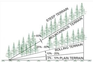
A hill road may be defined as the one which passes through a terrain with a cross slope of 25% or more. There may be sections along hill roads with the cross slope less than 25%, especially when the road follows a river route. Even then these sections are also referred to as hill roads. Hence, to establish a hill road overall terrain must be taken into account.
The hilly regions generally have extremes of climatic conditions, difficult and hazardous terrains, topography and vast high altitude areas. The region is sparsely populated and basic infrastructural facilities available in plain terrain are absent. Hence, a strong stable and feasible road must be present in hilly areas for overall development of other sectors as well.
IRC:SP:73-2015 and IRC:SP:84-2014 have merged the Mountainous and Steep Terrain having Cross Slope more than 25%.
2. Design Issues in Hill Roads
Design and Construction of Hill roads are more complex than in plain terrain due to factors summarized below:
Highly broken relief with vastly differing elevations and steep slopes, deep gorges etc. which increases road length.
The geological condition varies from place to place.
Variation in hydro-geological conditions.
Variation in the climatic condition such as the change in temperature due to altitude difference, pressure variation, precipitation increases at greater height etc.
High-speed runoff due to the presence of steep cross slopes.
Filling may overload the weak soil underneath which may trigger new slides.
Need of design of hairpin bends to attain heights.
Need to save Commercial and Residential establishments close to the road.
Need to save the ecology of the hills.
3. Special Consideration in Hill Road Design
a – Alignment of Hill Roads
The designer should attempt to choose a short, easy, economical and safe comforting route.
b – General considerations
When designing hill roads the route is located along valleys, hill sides and if required over mountain passes.
Due to complex topography, the length of the route is more.
In locating the alignment special consideration should be made in respect to the variations in:
Temperature
Rainfall
Atmospheric pressure and winds
Geological conditions
Resettlement and Rehabilitation considerations
Environment Considerations
c – Temperature
Air temperature in the hills is lower than in the valley. The temperature drop being approximately 0.5° per 100 m of rising.
On slopes facing south and southwest snow disappears rapidly and rain water evaporates quickly while on slopes facing north and northeast rain water or snow may remain for the longer time.
Unequal warming of slopes, sharp temperature variations and erosion by water are the causes of slope failure facing south and southwest.
d – Rainfall
Rainfall generally increases with increase in height from sea level.
The maximum rainfall is in the zone of intensive cloud formation at 1500-2500 m above sea level. Generally, the increase of rainfall for every 100 m of elevation averages 40 to 60 mm.
In summer very heavy storms/cloud burst may occur in the hills and about 15 to 25% of the annual rainfall may occur in a single rainfall. The effects of these types of rainfall are serious and should be considered in design.
e – Atmospheric pressure and winds
Atmospheric pressure decreases with increase in elevation.
At high altitudes, the wind velocities may reach up to 25-30 m/s and depth of frost penetration is also 1.5 to 2 m.
Intensive weathering of rocks because of sharp temperature variations.
f – Geological conditions
The inclination of folds may vary from horizontal to vertical stratification of rock. These folds often have faults. Limestone or sandstone folds may be interleaved with layers of clay which when wetted may cause fracturing along their surface. This may result in shear or slip fold.
The degree of stability of hill slopes depends on types of rock, degree of strata inclination or dip, occurrence of clay seams, the hardness of the rocks and presence of ground water.
When locating the route an engineer must study the details of geological conditions of that area and follow stable hill slopes where no ground water, landslides, and unstable folds occur.
g – Resettlement and Rehabilitation
Due to limited availability of flat areas and connectivity issues, most of the residential and commercial activity happens very close to the road leading to large scale R&R and becomes a challenge in alignment design.
h – Environment
Hills are ecologically sensitive areas relatively untouched by human activity. The alignment design must attempt to minimize tree cutting and large scale earth filling/cutting to minimize damage.
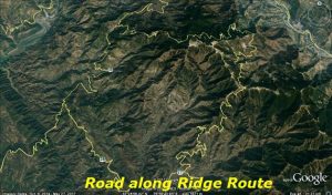
4. Route Selection
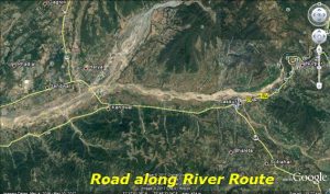
Hill road alignment may follow alignment at Valley bottom or on a ridge depending on the feasibility of the road. The first is called River route and the second is called Ridge route.
a – River route
Most frequent case of hill alignment as there is a great advantage of running a road at a gentle gradient.
Runs through lesser horizontal curvature.
Requirements for the construction of bridges over tributaries.
Construction of special retaining structures and protection walls on hill side for safe guarding the road against avalanches in high altitude areas.
Benefit of low construction cost and operation cost.
b – Ridge route
Characterized by the very steep gradient.
Large number of sharp curves occurs on the road with hair pin bends.
Extensive earthwork is required.
The requirement for the construction of special structures.
High construction and operation cost.
5. Engineering Data for Design
The design data includes:
The terrain classification all along the alignment – to be established through topographic data/ Contours of the area using Satellite Imagery.
All features like river course, streams, cross-drainage structures (for existing alignment), flooding areas, high flood levels, landslide areas, snow/avalanche prone areas etc.
River Morphology and Regime data.
Chainage wise inventory of the side slope material type i.e. soil with classification and properties, rock type and its structural geology of the area.
Hydrological data for all stream and river crossings.
Available material and resources that can be used in the road construction.
Geometric standards.
6 – Geometric Design Standards
a – Hill Road Capacity
Type of Road
Design Service Volume in PCU per day
As per IRC:SP:48-1998 and IRC:52- 2001
As per IRC:SP:73-2015 & IRC:SP:84-2014
For Low Curvature (0-200 degrees per km)
For High Curvature (above 0-200 degrees per km)
Level of Service ‘B’
Level of Service ‘C’
Single lane
1,600
1,400
–
–
Intermediate lane
5,200
4,500
–
–
Two Lane
7,000
5,000
9,000
–
Four Lane
–
–
20,000
30,000
b – Design Speed:
The design speed for various categories of hill roads are given below:
Road Classification
As per IRC:SP:48-1998 and IRC:52- 2001
As per IRC:SP:73-2015 & IRC:SP:84-2014
Mountainous Terrain
Steep Terrain
Mountainous and Steep Terrain
Ruling
Minimum
Ruling
Minimum
Ruling
Minimum
National and State Highways
50
40
40
30
60
40
Major District Roads
40
30
30
20
–
–
Other District Roads
30
25
25
20
–
–
Village Roads
25
20
25
20
–
–
c – Sight Distance:
Visibility is an important requirement for safety on roads.
It is necessary that sight distance of sufficient length is available to permit drivers enough time and distance to stop their vehicles to avoid accidents.
Design Speed (Km/h)
As per IRC:SP:48-1998 and IRC:52- 2001
As per IRC:SP:73-2015 & IRC:SP:84-2014
Mountainous and Steep Terrain
Stopping Sight Distance (m)
Intermediate Sight Distance (m)
Safe Stopping Sight Distance (m)
Desirable Minimum Sight Distance (m)
20
20
40
–
–
25
25
50
–
–
30
30
60
–
–
35
40
80
–
–
40
45
90
45
90
50
60
120
60
120
60
–
–
90
180
d – Minimum Radius of Horizontal curves
Classification
As per IRC:SP:48-1998 and IRC:52- 2001
As per IRC:SP:73-2015 & IRC:SP:84-2014
Mountainous terrain
Steep terrain
Mountainous and Steep
Area not affected by snow
Snow Bound Areas
Area not affected by snow
Snow Bound Areas
Ruling Minimum
Absolute Minimum
Ruling Minimum
Absolute Minimum
Ruling Minimum
Absolute Minimum
Ruling Minimum
Absolute Minimum
Desirable Minimum Radius
Absolute Minimum Radius
National Highway and State Highways
80
50
90
60
50
30
60
33
150
75
Major District Roads
50
30
60
33
30
14
33
15
–
–
Other District Roads
30
20
33
23
20
14
23
15
–
–
Village Roads
20
14
23
15
20
14
23
15
–
–
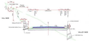
e – Typical Cross-sections – 2 lane carriageway (as per IRC:SP:73-2015)
f – As per IRC:SP:48-1998 and IRC:52- 2001
Road Classification
Carriageway Width (m)
Shoulder Width (m)
National and State Highways
i) Single lane
3.75
2 x 1.25
ii) Double Lane
7.00
2 x 0.9
Major District Roads and Other District Roads
3.75
2 x 0.5
Village Roads
3.00
2 x 0.5
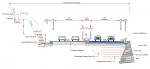
i –Typical Cross-sections – 4 Lane Carriageway Widening Towards Valley Side (as per IRC:SP:84-2014)
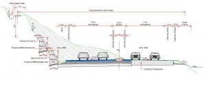
j –Typical Cross-sections – 4 Lane Carriageway Widening Towards Hill Side (as per IRC:SP:84-2014)
TOP 4 MAJOR CHALLENGES WITH FINITE ELEMENT ANALYSIS
The Finite Element Analysis is an amazing process in which the simulation of any physical object is done by leveraging the mathematical technique known as Finite Element Method (FEM). This technique improves the product manufacturing to a greater precision.
By using the extensive finite element analysis services, optimization of product design is possible by redesigning and eliminating the flaws present in the previous prototype. All in all, this is an unskippable technique used by every industry to ensure best product quality. But this perfect technique also possesses some of the major challenges on which engineers are working.
HERE ARE TOP 4 MAJOR CHALLENGES WITH FINITE ELEMENT ANALYSIS:
Stress Concentration Challenge:
The FEA is not that accurate when it comes to stress concentration testing. In stress concentration, there is a greater stress on the material of a very small area. These occur because of the frequent changes in equipment geometry. The stress in such areas may be greater than the yield strength of the material. However, this is not ideal when it comes to perfectly implementing the 3d mechanical drawing.
Time Consuming:
This process of analyzing physical object takes too many parameters for giving the results and improvements. Finite element analysis is a complex process and requires higher time for compilation as compared with other similar methods. When comparing FEA with FEM (Finite Element Method), it is slightly slower than FEM. The complexity of this process goes up even more when it is running with other practices like 3d scanning services.
FEA Needs Higher Configuration System :
This may be an issue if you want to do finite element analysis on a normal configuration system. As this process takes numerous inputs for generating different results, it demands a higher configuration system which can run multiple finite element analysis queries easily without any interruption. This may be a challenge for many who are trying to use this technique on lower configuration systems as compared to running normal AutoCAD drafting services.
The Final Results May Varies In FEA:
This is the challenge which bothers the engineers the most. The final result after processing may vary due to various factors. The factors such as material property, the stress and fatigue property of the material and many similar factors alter the final result of the test as compared to similar other techniques. If you are also looking for efficient FEA or cad outsourcing company, you must reach to us.