Mechanics of Civil Engineering Structures Free PDF
Practicing engineers designing civil engineering structures, and advanced students of civil engineering, require foundational knowledge and advanced analytical and empirical tools.
Mechanics in Civil Engineering Structures presents the material needed by practicing engineers engaged in the design of civil engineering structures, and students of civil engineering.
The book covers the fundamental principles of mechanics needed to understand the responses of structures to different types of load and provides the analytical and empirical tools for design.
The title presents the mechanics of relevant structural elements – including columns, beams, frames, plates and shells – and the use of mechanical models for assessing design code application.
Principales And Practice Of Ground Improvement Free PDF
By Jie Han
Ground improvement is popular in many countries to solve difficult geotechnical problems, especially when construction necessarily occurs in problematic soils and under difficult geotechnical conditions.
Many recent developments in equipment, materials, and design methods have made ground improvement technologies more effective, efficient, and economic. However, the state of practice for most ground improvement technologies is that the practice is ahead of theory. Some contractors have developed their proprietary technologies, design methods, and construction techniques for their competitive advantages.
Most of the existing books on ground improvement are focused on the concept, application, and case study. However, few books have been devoted to the principles and design methods of ground improvement. This book covers both theoretical and practical aspects in the design and construction of a variety of ground improvement technologies commonly used in practice.
Corrosion is generally taken to be the wastage of a metal by the action of corrosive agents. However, a wider definition is the degradation of a material through contact with its environment. Thus corrosion can include non-metallic materials such as concrete and plastics and mechanisms such as cracking in addition to wastage (i.e. loss of material).
In essence, the corrosion of metals is an electron transfer reaction. An uncharged metal atom loses one or more electrons and becomes a charged metal ion.
In an ionizing solvent the metal ion initially goes into solution but may then undergo a secondary reaction, combining with other ions present in the environment to form an insoluble molecular species such as rust or aluminium oxide. In high-temperature oxidation the metal ion becomes part of the lattice of the oxide formed.
As the OWTs are located on the sea, therefore, support structure and its foundation are important for design considerations.
There are several conventional bottom-mounted support structures, which can be categorized into five basic types:
monopile structures (using pile foundation),
tripod structures (using pile foundation),
lattice structures (using pile foundation),
jacket foundations,
gravity structures,
floating structures.
There are also hybrid support structures which use the combined features of the above categorized structures. For the first three type of supporting structures (monopole, tripod, lattice structures) pile as the foundation is usually used. Pile foundations are one of the most common forms of offshore structures; they are widely used for both offshore oil platform and OWT.
The standard method of piling method is to lift or float the structure into position and then drive the piles into the seabed using either steam or hydraulic powered hammers.
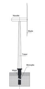
1. Monopile Structures
As shown Fig.1, monopole has the simple fabrication and installation.The tower of the turbine directly sits on one pile. Monopile foundations are one of the most frequently used support structure to date. Most of the offshore wind farms in shallow waters are monopole structures, which have the advantage of simple design for manufacturing.
However, failure of the grouted connections between the monopile andthe transition piece is one of its disadvantages. This transition piece is responsible for connecting the monopile to the turbine tower. In addition, there is no proven solution using monopiles for larger turbines with 5 MW or more powerful turbines.
Fig. 1. Wind turbine on the monopile foundation
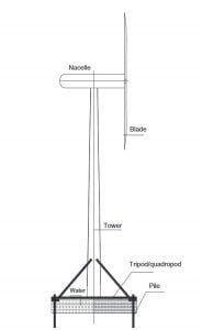
2. Tripod and Lattice
As shown in Fig.2, the turbines directly sit on a tripod or a lattice, which are supported on the pile foundations. The tower can be further stabilized by the tripod.
Fig.2. Wind turbine on tripod
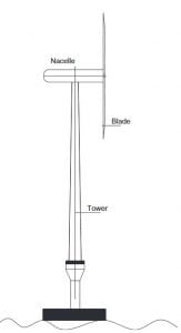
3. Gravity Foundations
As shown in Fig.3, this type of foundation achieves its stability solely by providing sufficient dead loads by means of its own gravity. Ballast can be pumped-in sand, concrete, rock, or iron ore to add extra weight. Gravity structures are suitable for modest environmental loads such as wave load that are relatively small and dead load is significant or when additional ballast can easily be provided at a modest cost.
The gravity base structure is especially suited where the installation of the support structure cannot be performed by a heavy lift vessel or other special offshore installation vessels, either because of non availability or prohibitive costs of mobilizing the vessels to the site.
Gravity-base foundations are the second most popular sort of support structure to date. They have been used mostly to support smaller turbines in shallow waters near shore locations with a rocky seabed where the operation of piling is extremely complicated and expensive. However, for waterdepth beyond 35 m, the new generation of wind farms are needed.
Fig.3. Wind turbine on the gravity-base foundation
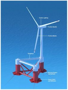
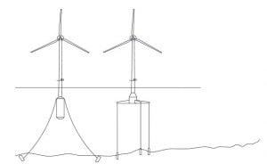
4. Floating Structures
Floating structures are especially competitive at large water depths where the depth makes the conventional bottom-supported structures non-competitive. Detailed design guideline can refer to DNV-OS-J103,” Design of Floating Wind Turbine Structures”.Fig.4 shows a floating form using space frame style floater.Fig.5 gives the other two examples.
Fig.4. Floating wind turbines
Fig.5 Floating wind turbines examples
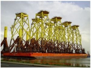
5. Jacket Foundations for Offshore Wind Structure
As shown in Fig.6, jacket foundation uses four-legged jackets to supportthe OWTs, which can support larger OWTs such as 6 MW turbines. Jacket foundations provide a solution for foundations in offshore wind farms in water depths of 35 m and beyond which is less risky, less expensive, and more reliable than monopiles and gravity-base foundations.
Elastic Analysis of Reinforced and Prestressed Sections Spreadsheet
The spreadsheet presented in the previous post in this series uses the basic equation given below to find the location of the neutral axis:
For a cross section with any applied axial load at eccentricity e, measured from the compression face, and depth of the neutral axis X below the compression face:
INA = QNA(X + e)
Where QNA and INA are the first and second moments of area about the neutral axis.
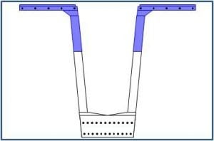
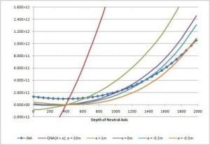
To illustrate this relationship the value of INA has been plotted for a range of neutral axis positions for a typical precast bridge beam, shown below, and compared with the value QNA(X + e) for 5 different values of e.
The intersection of the INA and QNA(X + e) lines gives the depth of the neutral axis for the corresponding value of load eccentricity, e. This is illustrated in the second graph, where the value of (INA – QNA(X + e)) is plotted against the depth of the neutral axis, X, for a load eccentricity of 1 metre above the compression face.
The intersection of this line with the X axis gives the depth of the neutral axis for the specified load eccentricity.
Note: Another calculation file ULS Design Functions.zip contains User Defined Functions (UDF’s) that will find the ultimate bending capacity of any reinforced or prestressed concrete section